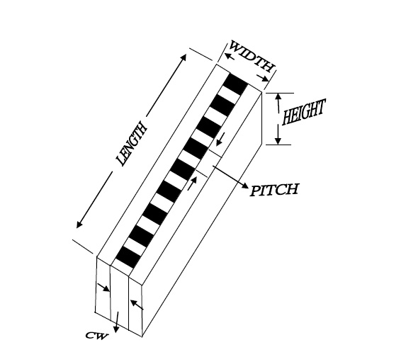

Length
1.0-2.0 mm shorter than length of the glass as the room for expansion after compressing
E.g.: If the LCD and the PCB have many pins extending to the two ends, more the interconnector left and right to make sure that the interconnector is longer than the last pin of the module.
Height
The length between PCB and LCD plus the compression ratio E.g.: If the after compressing length between PCB and LCD is 5.0mm, the reasonable compression ratio is min 9%, max 13%, and mid 11% is suggested to take for the design.
Distance between PCB and LCD
Length design= compression height x (1+compression ratio) = 5mm x (1+0.11) =5.55mm
NOTE: When contact width (CW) bigger than 0.8mm, width longer than 3.0mm, or the hardness of the side insulation part higher than 25°, the compression ratio needs to be proportionally decreased.
Width
When the width is shorter than 3.0mm, the tolerance set as ±0.1mm When the width is longer than 3.0mm, the tolerance set as ±0.15mm
Width design suggested formula
Width=inner edge of the frame — down side of the glass ÷ 2 x 0.85 (high compression) Width=inner edge of the frame — down side of the glass ÷ 2 x 0.90 (low compression)